Athletic Fields
Drainage Installation Advice for Athletic Fields
A. Natural turf
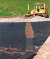
1. Trenching
In most natural turf situations, it is best to install Multi-Flow vertically. A 4 inch wide trench is ideal both for performance and ease of installation. It produces little spoil and results in excellent drainage because it takes advantage of Multi-Flow’s significant vertical footprint. Installations that use a combination trencher/conveyor can trench and remove spoil in one efficient operation.
2. Layout pattern
a. Crowned or sloped fields.
If the surface of the field has a consistent slope (greater than .5%), it is advised that the collector lines be placed such that they intersect the water flow direction. Placing the lines at a 90 degree angle to the flow direction and running toward the end zone is usually not the best policy. The resulting lines would be too long and, in order to maintain fall, excessively deep. A 45 degree angle running toward the sidelines works well because it allows the lines to maintain grade while also intercepting the direction of surface water flow. The resulting herringbone pattern complements the existing field contour, providing effective drainage as well as an uncomplicated installation.
b. Flat or irregular fields.
If the field is flat, or has less than a .5% slope from the center, then a parallel drainage pattern may be appropriate. Since the water will basically stand on the surface of a flat field, there is no advantage in attempting to place drainage lines in the flow path. Collectors could run toward the sidelines or the center of the field. On flat fields, proper grade needs to be maintained by increasing the depth of the trench.

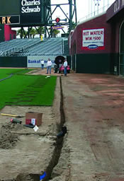
3. Coverage
The drainage pattern should extend 10 to 15 feet beyond the field to include the intensively used sideline area. 6-inch Multi-Flow is ideal for these on-field collectors. It is also advisable to run 18-inch Multi-Flow lines along the sides of the field or all around the field. These lines will collect water that might run toward the field from the outside and provides supplemental drainage to the sidelines. It also cuts down on the number of connections that are needed to the transport system. If 18-inch Multi-Flow is run parallel to the sidelines, or sidelines and end zones, then the 6-inch collectors used in the playing area can empty into the 18-inch lines using an 1800P (Y left) or an 1800Q (Y right).
4. Collector line spacing
Placing collector lines 10 feet apart, outlet to outlet, provides excellent reaction time and uniform drainage performance. 15 feet apart provides an adequate system. A field employing 20 foot spacings will require a longer waiting period before use after a rainfall event.
An example will illustrate the consequences of line spacings. Assume 40 lines of 6-inch Multi-Flow in an area 210 feet by 400 feet (10 foot spacings). This will provide capacity to handle a maximum of 1.56 inches an hour, assuming:
- 17 gpm x 40 lines = 680 gallons per minute each side of the field.
- 680 gpm x 2 sides = 1,360 gallons per minute.
- 1360 gpm x 60 minutes = 81,600 gallons per hour.
- 210 feet by 400 feet = 84,000 ft2
- 81,600 gph / 84,000 sq./ft. = .971 gallons per sq./ft. per hr.
- .971 gal./sq. ft./hr. = 1.56 inches of rainfall per hour (.971/.623)
Capacity could be increased by adding more Multi-Flow drainage lines.
Three factors will determine the line spacing decision:
1) anticipated schedule 2) local rainfall events 3) project budget
5. Transport system
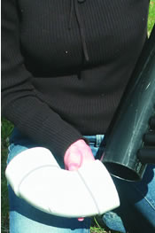
Due to strength and flow rate requirements, a smooth wall pipe makes for the best transport system. PVC pipe is commonly used. A standard PVC elbow or tee can be slipped over a Multi-Flow connector.
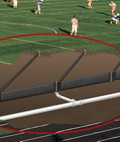
To design a transport system it is necessary to calculate the total drainage system capacity. For an example, let’s again assume forty lines of 6-inch Multi-Flow in an area 210 feet by 400 feet. If the field is crowned and laid out in a herringbone pattern, these lines will empty into the transport system on both sides of the field. So effectively, there are eighty collector lines. If each carried 17 gallons per minute, these eighty lines could deliver 1,360 gallons a minute or 81,600 gallons an hour. Sideline drains could increase that amount. Leaving the site, this would require a minimum of one 12-inch or two 8-inch PVC pipes.
If an 18-inch Multi-Flow is used as a collector line along the two side lines, and the 6-inch collectors empty into these 18-inch lines (using 1800P or 1800Q connectors), then it will be necessary to tap into the 18-inch line at calculated intervals in order to accommodate the volume of water. To calculate that interval, assume the following:
- 6-inch Multi-Flow = 17 gallons per minute.
- 18-inch Multi-Flow = 47 gallons per minute.
- 1800P or 1800Q = 112 gallons per minute.
- 4-inch PVC = 112 gallons per minute
Based on the above assumptions the 18-inch line should be emptied into the transport system once for every six or seven lines of 6-inch Multi-Flow. This is accomplished by attaching an elbow or a tee to the bottom of every sixth or seventh 1800P or 1800Q. The 18-inch perimeter drain is installed without a slope so the outlet to the transport line will be accepting water from both directions. Keep in mind that when the system is at full capacity there will be substantial head pressure on the system which will increase the flow rates of all components.
It is common to step up the size of the transport pipes as they proceed down the field, thus avoiding the cost of unnecessary large PVC connectors. A 4-inch PVC can carry 112 gallons of water a minute (1% slope, no head pressure) so it would be adequate for handling water from the first six collector lines. A 6-inch PVC would be suitable for carrying the previously collected water plus the water from the next thirteen collector lines. An 8-inch PVC could do the job the rest of the way down the field.
Assuming the 210 X 400 foot field from the example, if the 18-inch collectors are employed, it will empty into the collector system from an 1800P at six to seven locations along the left side of the field and from an 1800Q at six to seven locations along the left side of the field. Without the 18-inch collectors, each of the forty collector lines would empty directly into the collector lines on both sides of the field.
Transport pipes can be located beneath the sideline drain or in a separate trench beyond the sideline drain. The second option is generally more efficient and cost effective.
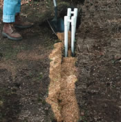
6. Backfilling
Backfill material may be the single most important factor affecting the longevity of a drainage system. Sand can function as a filtration device, removing silt and clay particles, while allowing water to pass through. Clay or silt spoil excavated from the trenches should be removed from the site. Trenches should then be backfilled with a clean very coarse sand, nearly to the surface. To eliminate voids in the backfill, trenches can be jetted with water or settled with a vibratory compactor after all connections have been made.
B. Synthetic turf
1. No trenching required
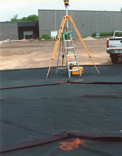
In most synthetic turf situations, it is best to install Multi-Flow flat. Collector lines can be positioned horizontally directly on the compacted base, or on top of the geotextile soil separator if one is used. No costly and time consuming trenching is necessary.
2. Layout pattern
Synthetic turf fields typically have a consistent center to sideline slope. Collector lines should be placed such that they intersect the water flow direction. Placing the lines at a 90 degree angle to the flow direction and running them toward the end zone is not the best policy because the resulting lines would be too long. A 45 degree angle running toward the sidelines works well because it allows the lines to maintain grade while also intercepting the direction of surface water flow. The resulting herringbone pattern complements the existing field contour providing effective drainage as well as uncomplicated installation. This drainage pattern should extend all the way to the edge of the synthetic turf so it will include the intensively used sideline area. Transport lines should be located at the edges of the field.
3. Collector line spacing
The coarse sand and rock used in synthetic turf fields is capable of absorbing substantial amounts of water. Consequently, it is acceptable to allow more time for desaturating the base of a synthetic field than a natural turf field and as a result, collectors can be spaced farther apart. Placing collector lines 15 feet apart, outlet to outlet, provides excellent reaction time and uniform drainage performance. Twenty feet apart provides an adequate system. A field employing 25 foot spacings will require significantly longer to drain after a rainfall event. It would be unwise to space them farther apart because allowing water to set on the compacted base for prolonged periods of time will soften the subgrade and destabilize the base.
An example will illustrate the consequences of line spacings. Assume twenty-seven lines of 6-inch Multi-Flow in an area 210 feet by 400 feet (15 foot spacings). This will provide the capacity to handle a maximum of 1.05 inches an hour, assuming:
- One 6-inch Multi Flow can carry 17 gallons per minute.
- 17 gpm x 27 lines = 459 gallons per minute each side of the field.
- 459 gpm x 2 sides = 918 gallons per minute.
- 918 gpm x 60 minutes = 55,080 gallons per hour.
- 210 feet by 400 feet = 84,000 ft 2
- 55,080 gph / 84,000 sq./ft. = .656 gallons per sq./ft. per hr.
- 656 gal./sq. ft./hr. = 1.05 inches of rainfall per hour (.656/.623)
System capacity can be increased by adding more Multi-Flow drainage lines.
Five factors will contribute to the spacing decision:
- anticipated intensity of field use
- local rainfall events
- project budget
- stability of the subgrade
- particle size of the select aggregate base
4. Transport system
Many synthetic turf installers and designers call for a perimeter trench containing a perforated transport pipe. Multi-Flow collector lines either empty into this drained perimeter trench or are connected directly to the transport pipe at perhaps 15 or 20 foot intervals. This method has worked well on many fields.
A more efficient system employs an 18-inch Multi-Flow line installed vertically along each side of the field. The 6-inch collector lines connect directly to these 18-inch sideline collectors. Accumulated water is then emptied directly into a parallel collector line after each six or seven inlets as in a natural turf system.
Because of strength and flow rate requirements, a smooth wall pipe makes for the best transport pipe. To design an adequate transport system it is necessary to first calculate the total drainage system capacity. For example, let’s again assume twenty-seven lines of 6-inch Multi-Flow in an area 210 feet by 400 feet. If the field is crowned, these lines will empty into the transport system on both sides of the field. So effectively, there are fifty-four collector lines. If each is capable of carrying 17 gallons per minute, these fifty-four lines could deliver 918 gallons a minute or 55,080 gallons an hour. Leaving the site, this would require a minimum of one 10-inch or two 8-inch smooth wall transport pipes. It may be advisable to build in additional capacity for water that enters the perimeter trench through other means such as catch basins.
- It is acceptable to step up the size of the transport pipes as they proceed along the perimeter trench.
- A 4-inch PVC can carry 112 gallons of water a minute (1% slope, no head pressure) so it would be adequate for handling water from the first six or seven collector lines.
- A 6-inch PVC can carry 327 gallons of water a minute (1% slope, no head pressure) so it would be suitable for carrying the previously collected water plus the water from the next thirteen collector lines.
- An 8-inch PVC can carry 704 gallons of water a minute ( 1% slope, no head pressure) so it could do the job the rest of the way down the field.
5. Backfilling
Backfill material may be the single most important factor affecting the longevity of a drainage system. Sand functions as a filtration tool, removing silt and clay particles, while allowing water to pass through. A 2-inch band of very coarse sand should be installed covering the top and sides of each collector line.
This sand backfill could be eliminated if the select aggregate is free from silt and clay, but this is seldom the case. See Selecting Backfill Material for more information on this topic.