Golf Courses
Drainage Installation Advice for Golf Courses
I. Multi-Flow in vertical installations
A. Design
1. Trenching
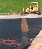
Effective drainage of fairways and along cart paths is usually best achieved with a vertical Multi-Flow installation. Bunkers are often drained this way as well. Vertical installations provide a sizable intercept area but leave only a narrow scar in the turf. A 4 inch wide trench is optimal. Depth will be determined by factors such as:
- anticipated depth of maintenance practices
- desired depth of desaturation
- width of area to be drained
- required response time
- speed at which full drainage is desired
- subsurface physical features
- the location of irrigation lines.
2. Line length and spacing
On a level surface, subsurface drainage of turf is most effective within 5 to 8 feet of the drain line. Therefore, 10 to 16 foot spacings are ideal. On sloped surfaces a wider spacing is acceptable because gravity will aid in bringing water to the drain line. In fairways, a central collector line running up the center with arms reaching out into low-lying areas on either side, is frequently the best course of action.
3. Product size selection
A line of 6-inch Multi-Flow could reach capacity in about 150 feet of water collection. 12-inch Multi-Flow could drain up to 235 feet of length before it reaches capacity. While 18-inch Multi-Flow could extend up to 360 feet. These lengths are based on the assumption that the line is collecting water from a 12 foot wide area during a one inch in one hour rainfall event.
4. Transport system
After water has been collected by the Multi-Flow system, it must be transferred to a transport system for its journey from the site. This maximizes the total output of the system in a given amount of time. Sometimes the water is discharged into a storm sewer, stream or pond. Increasingly, it is collected for reuse in irrigation.
The transport lines need to have a carrying capacity at least equal to the sum of all of the collector lines they are called on to service. For planning purposes it is useful to assume these numbers:
If there is any danger that the water level at the discharge point will rise higher than the level of the collection system, a check valve should be installed on the discharge pipe. This will prevent contaminated water from backing up into the collector lines and causing siltation.
B. Installation
1. Equipment needed:
- 4-inch chain trencher and trenching spade
- turf utility vehicle
- utility knife
- laser level
- centering device(s) (optional)
- water and/or vibratory packer (optional)
2. Materials needed:
- appropriate size of Multi-Flow pipe for collector system
- appropriate Multi-Flow connectors
- clean, very coarse sand
- PVC or ABS pipe for transport system
- PVC or ABS adaptors if needed
- PVC tape
3. Trenching
Plot a path through the problem area to a desired discharge point marking the path with paint or flags. Begin trenching at the discharge point and proceed toward the highest point of the problem area. Measure regularly to ensure that you are maintaining a proper grade. A laser level or transit is a useful tool in this situation.
If the excavated material contains clay, remove it from the site before installing the drain.
4. Laying out the drain
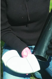
Roll out the drain beside the trench. At the ends, pull back the geotextile filter and snap the connectors in place. Connectors slip on more easily if they are manually pre-stretched. Push the fittings, such as end caps, couplers, side outlets or end outlets, firmly over the pipe to ensure a secure fit.
Then pull the fabric over the fitting and hold it in place with PVC pipe tape. This ensures that soil will not enter behind the fabric and block the drain core during placement.
Do not place Multi-Flow into a trench that contains standing water.
C. Connecting to transport system
Usually connection to the transport system will be made with a multi-purpose connector. Most commonly this will be a 0600M, 1200M, or 1800M. These connectors empty from the bottom. Smooth, solid, rigid pipe makes for the most reliable transport system. Use of pipe cement will ensure a lasting connection. Multi-purpose connectors join to 3-inch PVC elbows and tees.
In some situations it is preferable to discharge the water through an end outlet or a side outlet (e.g. 06003 or 06004). In these cases, cut the plastic membrane covering the opening of the outlet so that the exit pipe fits in snugly and is located at the bottom of the fitting. Insert the exit pipe and seal the joint using PVC pipe tape to prevent soil intrusion. 6-inch Multi-Flow connectors attach to a 3-inch PVC while 12 and 18-inch Multi-Flow match 4-inch PVC.
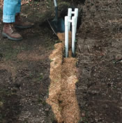
D. Backfilling
Use clean very coarse sand to fill the trench. Hold Multi-Flow in the relative center of the trench while backfilling. Centering devices are helpful in this task. Bring the sand up to the surface or near to it. Jetting the sand-filled trench with water will help to settle the sand in place more quickly. A small vibratory packer also works well.
Topsoil can be blended with the sand at the surface of the trench to create a better turf growing medium. Never, however, cap the trench with clay or other dense impermeable material. For more information on this topic see Selecting Backfill Material.
II. Multi-Flow in horizontal installations
A. Think it through before you start.
A horizontal placement of Multi-Flow is usually the most effective way to design drainage in a new golf green. Before exploring this method, we will first discuss green drainage in a more general way.
Whether you are dealing with a USGA-style layered green, a California-style single material green, or even a pushup-style green, an effective subsurface drainage system is a must. Assuming that the green has been constructed using porous materials, water will soon arrive at the relatively impermeable subbase. If it does not have an easily accessible escape route from here, the green will become saturated. This invariably results in unacceptable growing and playing conditions.
Three primary considerations influence subsurface golf course green drainage plans and practices:
- Does the system provide adequate drainage?
- Will the system be damaged by maintenance practices?
- Will the system avoid future failure and blockage?
Multi-Flow addresses these concerns by providing systems that are: 1. low profile, 2. intensively patterned, and 3. adequately filtered.
1. Low profile
Multi-Flow’s structure and shape provide unique drainage advantages. Its flat profile provides superior surface area allowing more opportunity for water to enter the system. Its superior strength significantly reduces the risk of being crushed. And its internal flow characteristics allow water to leave the green area quickly.
Furthermore, it need not be trenched in but is simply rolled out over the subgrade where it lies out of reach of cup cutters and coring equipment.
2. Intensively patterned
Conventional wisdom has often placed drainage collector lines only in the low points of the green subbase. The assumption was that since water will find these low-lying areas anyway and since greens allow water to move freely, this is all that is necessary.
This practice overlooks the effect that moving water has on the structure of the green. Moving water carries fine particles with it. The more water that moves and the higher velocity at which it moves, the more soil it will carry with it. Installing drain lines further apart requires that water move in greater volume to fewer collection points. This results in greater soil migration which causes a break down of the soil structure and a potential blocking of drainage lines.
Drainage on a golf green should be gentle and thorough. Intensive patterning decreases the velocity of the water movement and consequently protects the fragile integrity of the green structure. Spreading drainage lines out over the entire subgrade of the green means that water has less distance to travel and results in less soil migration.
But locating lines closer together also ensures a prompt and thorough drainage. Look at the veins on the back side of a leaf for a model of effective drainage. The less distance water needs to travel to reach an escape route, the better the drainage is. Intensively patterned drainage allows for the removal of significant amounts of water in a short time without disrupting the structure of the soil.
3. Filtered
Two separate filters assure that the drainage system will not fail. Multi-Flow’s 4-ounce, needle-punched geotextile wrap prevents sand from entering the flow channels. Two inches of clean, very coarse sand effectively protects the geotextile from blockage due to silt and other soil fines.
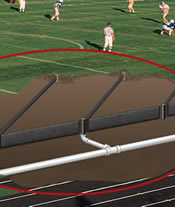
B. System design and layout
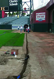
When designing drainage for a green, the main Multi-Flow collectors should lie horizontally on the subgrade and be placed along the line of maximum fall. A 4-inch PVC pipe should be placed directly below the main line, exiting the green at the low end. PVC tees must be installed in the PVC lines, pointing upward, at each location where a Multi-Flow double wye will connect to the laterals. The PVC pipe should be backfilled with native soil, leaving only the opening to the PVC tee exposed and lying flush with the soil surface.
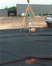
If a geotextile fabric is to be used as a barrier between unstable subsoil and the gravel drainage blanket as in a USGA green or between the subsoil and the green mix as in a California-style green, it should be installed at this time, and openings should be cut into the barrier fabric for the PVC tees to emerge through. Typically, the barrier fabric should not cover the Multi-Flow drainage product. Locate lateral Multi-Flow collectors across the slope of the subgrade, allowing a natural fall to the main line, where they will connect into the double wye.
Lateral lines should be spaced not more than 12 feet apart and extended to the perimeter of the green. Lines should be placed in water-collecting depressions, if they exist.
If the green exceeds 100 feet in width, an additional herringbone, or half herringbone, must be installed along one side of the original pattern in order to maintain maximum flows.
At the low end of the gradient, adjacent to the main line’s exit from the green, vertical drainage product should be placed along the perimeter of the green, extending to the ends of the first set of laterals. This smile drain will facilitate drainage of the water that may accumulate at the low end of that drainage area. The vertical drainage product can be discharged into the 4-inch PVC pipe by way of a Multi-Flow connector, such as a 06009, and a PVC tee as it exits the green.
C. System installation
1. Wherever the grade exceeds 3%, stakes should be placed to prevent movement of the Multi-Flow during later stages of construction.
2. Avoid applying more than 6,000 psf to the Multi-Flow during construction. Once the 2- inch band of sand is in place, additional pressure on the Multi-Flow is permissible.
3. The geotextile filter fabric should be securely taped to all fittings to prevent the infiltration of sand or soil during placement.
4. Maintain a grade of at least .5%; 1% is preferable.
5. If the PVC transport system terminates in a stream or pond that is likely to reach the height of the exit pipe, a check valve must be installed to prevent back flow through the drainage system.
D. Backfilling
Backfill material may be the single most important factor affecting the longevity of a drainage system. Sand functions as a filtration tool, removing silt and clay particles, while allowing water to pass through. A 2- inch band of very coarse sand should be installed covering the top and sides of each collector line.
This sand backfill could be eliminated if the select aggregate is free from silt and clay but this is seldom the case. See Selecting Backfill Material for more information on this topic.